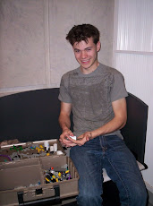
Hello Readers,
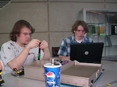
This months project is unfortunatly our last one. It will mainly involve the fields of mechanical and industrial engineering. This project is a pleasant reprieve from the Lego kits because now we get to use any materials that we want to!
The problem presented to us was to design and construct an automatic coin dispensing machine that should be capable of holding and automatically dispensing up to 20 US coins in less than 2 minutes. The main factors to be considered in the design are: accuracy, speed, cost, ease of use, and ease of manufacturing. We can use any materials that we like to build it, so long as our cost does not exceed 15$. Additionally, we can use lego parts at no cost. The whole machine must also fit into a 15 cm square box. The ringer is that the machine has to be automated. By that i mean that the user cannot touch the coin to remove it. The user has to press a button or lever of some type to have to coin pop out into their hand.
Next, we brainstormed ideas for how to solve the problem. We came up with many ideas that all had different benefits. We looked at pex dispencers; they use a spring to push up the pez and the top is a lever to push out the item. We considered the different types of coin machines used in supermarket lobbys. Some have sliding drawers and other have rotating slots with different sized holes. We made designs that consisted mostly of legos to keep the price down. We tried designing the best possible dispencer with no restraint of cost. Throughout the brainstorming process we had to keep in mind the main factors that they would be looking at when grading it.
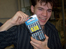
We came up with a Solution whose main quality was being cheap. Our dispencer was made at the total cost of $1.70 with no Lego parts. . We decided that the stacked tray or a machine made of Lego’s would be too problematic. The coins would be too hard to control in a file cabinet tray. And Lego’s just aren’t made to handle coins; mainly because they are so small. We chose to use the side by side PVC cylinder idea. We framed our idea off of the existing machines that are found in store lobbies. Machines like sticker dispensers devised a way for you to put money in. It has a flat sliding drawer with a hole the size of a coin in it. A person would put money in and slide the reverse dispenser under a blockade and into the machine. We decided to do just the opposite. The money would be stacked inside each of four separate PVC cylinders. The bottom would have the sliding drawers with the coin hole in it. To remove one single coin, a person would slide in an empty drawer causing a coin to fall in it, then he would simply slide the drawer back out with the coin in it.
We concluded that we discovered a very viable method of creating a coin dispencer. Our design is cheap, compact, semi-durable, effective, and it looks good. A negative issue is that it isnt as fast at dispencing as some other designs. We dispenced all of the coins within 44 seconds. Some models were able to do it under 20 seconds. Our design could have benefitted from spending a little more money to add bolts to it; this would make it amazingly durable.
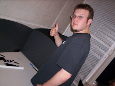
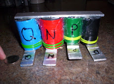
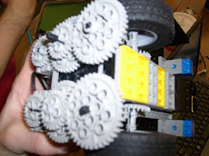
On a side note, we misunderstood the problem the first time we read it. Consequently, we designed and built a coin Sorting machine. We used 4 stacked trays with holes in them. When shaken the big coins are stuck at the top, and the little ones fall to the bottom. It is able to take a handful of random coins and sort them into four piles fast. Undortunatly, it isnt very fast at Dispencing, so we started over when we found out what the real project was. This explains the other pictures with the legos. this project only costed 5$. (we would have done well in competetion.)
Well thanks for taking the time to read about our work in our IME 106 engineering class at SIUE. Hopefully we were able to interest or educate you in some way through our work.
Thursday, May 1, 2008
Monday, April 14, 2008
Lego Robot: Transport The Cargo
Hello Reader,
This months project involves the lego mind storm kits again. This project will revolve around problems such that having mechanical, computer, and industiral engineers present would be beneficial.
This project's Problem is about designing and building a robot which will attempt to safely transport, without damage or loss, two ping-pong balls from the top a platform to a box separated by a given distance. The balls initially rest in two holes with a diameter of one centimeter each; the holes are ten cm apart on the top of a platform. The outside dimensions of the drop off box, where the ping-pong balls need to be placed, are L25xW15xH15 cm. The robot itself must be built within the maximum dimensions of L20xW20xH30 cm. The robot must be programmed to be fully autonomous. Its task is to deliver the ping-pong balls to the box as fast as possible within the time constraint of two minutes. Between the loading platform and the box is a line made of black tape. It will not be straight and will contain two T-joints. The robot must use this line to navigate the terrain. Time will start when the robot begins and will end when the last ball is dropped. Ideally this task will be done in the least amount of time.
Now we need to brainstorm posibilities for a solution using these guidelines.
First, we surveyed our options of data input and physical output to and from the robot. These variables will determine the main characteristics possible of any robot. The sensors available were two light sensors, two touch sensors, and one rotational sensor. Additionally, there were three motors available.
Second, we analyzed all of the physically possible ways for a robot to actually get control of the two ping-pong balls. We could use claws of come sort to hook them in toward a more controllable area. We drop some sort of mechanism on top of them. We could use a sort of shovel and scoop them up. Or some kind of back hoe shovel and scoop them inwardly.
Third, we had to keep in mind that the robot would have to physically lift the balls up fifteen cm into the box. There were rack and pinion gears available. They could lift up the whole front holding the balls. Once in the air they might be rolled off or dropped straight in. Or the gears could push off the ground, lifting the front of the robot into the air. We could set up a catapult and launch the balls into the box. We could use a special double gear sided bar which would allow us to rotate the ball holders upward.
Fourth, one of the constraints was that it had to follow the line in order to find the box. This means that we had to incorporate at least one light sensor. It can be done with one sensor so that every time the robot goes off the line, it turns until it is on it again. This saves the other two sensor input ports for other things. We could use two light sensors and separate them so the robot straddles the line. Though this would take up two input ports, and leave only one port for every other input that it may need.
Fifth, when the robot finds the box it needs to know what to do. It is possible that it may find the box at an angle, which could lead to balls not landing in the box properly. If we choose the line following program with two light sensors, then the robot will have to find a way to react properly to the box with only one input port available. Another design decision lies in the choice of propulsion. We have tires of varying sizes as well as two conveyor belt treads. If we choose to use one motor for propulsion we will have to set up a series of differential gears to allow the robot to turn. Additionally, with this form of movement we would have to add a separate motor to a steering column. Or some sort of reverse and turn mode to save the use of a motor. Other options included allotting one motor for each tire or tread. Doing this would allow the robot to make zero degree turns.
Our Solution: After much deliberation upon which designs would be the most effective, we combined what we think are the best ones that will work together.
We built a robot that has a button sensor on one side, and a lift on the other. It will aproach the two balls and lower a one way container over it. The balls will pop through rubber bands and be trapped in the container. Then the robot will use two light sensors to navigate through the course. Upon reaching the box, the robot will move forward until the button is pressed, the robot will know that it is near the box. We will program it to first lift the balls all the way to the top of the lift. Then the whole robot would rotate 180 degrees and move backward. This will bring the container right up to the edge of the box. Then the robot will lower the container, and speical pushing lever will push the balls out of the container. They will roll forward and fall into the box.
We concluded that our design is a very effective method of solving the problem. Our effective use of light sensors and motors will give us very good chances of navigating the course quickly and efficiently. Our choice of ball pick up, lifting, and removal methods all rely on simple machines. The rubber bands will always do the same thing every time the experiment is performed. They will grab the ball every time the lift falls over them. Other rubber bands will allow container to slide past the slide-pushers and they will move back into the proper position every time. We even designed the robot to lift the balls high enough and have exit ramps. This solves the problem of the robot not finding the box at a right angle.
Another way this could have been done effectivly is with a similar design could have been used that may have worked just as effectively. We could have used grabbing arms to get control of the balls. This would give us more room for error in the programming of the robot to approach the balls. They would have been geared to the same motor as the rack and pinion gears attached to the lift. To stop the claws from grabbing into itself and jamming, we could have used gears with only half the teeth. Then the motor could not possible close the claws too far and would in fact work to hold on to the balls. The claws would have had gates that keep the balls in the proper position until they would be forced out at the top. However, we think that the method we used is more effective due to its simplicity.
Monday, March 24, 2008
Lego Robot: 'Push the Cans'
Hello Readers,
This week the team gets to work on a Lego Robot. This project will involve mechanical design and computer programming.
Let's start out with an explanation of what we are doing here. This project is about designing and building a robot which will attempt to detect cans of varying weights placed randomly in a 4’ diameter circle and move the cans in the center in a 1.5’ diameter circle. Both circles would be defined by black tape. The robot has three minutes to collect as many cans as possible. During this time it must stay inside of the 4’ ring. The robot must be made entirely out of the Legos provided by the instructor. The robot must be fully autonomous, running off of a pre-programmed set of instructions also created by the students. The robot must be able to fit within a 20 by 20 cm. square and it may not expand in size after beginning. The total weight of the robot must be less than 1 kilogram.
We had to take all of the constraints into consideration when we went through our brain storming process. Even with them holding us back, there were still a lot of options available for the design of the robot.
First, we surveyed our options of physical input and output to and from the robot. These variables will determine the main characteristics of any robot. The sensors available were two light sensors, two touch sensors, and four rotational sensors. Additionally there were three motors available.
Second, we analyzed all of the physically possible ways for a can to be moved from its location to the center of the ring. It can be grabbed one at a time and taken directly to the center. It can be scooped up or pushed. It can be picked up and stored to be dropped off later. And it can be knocked over and rolled to the center.
Third, we would have to keep in mind that the cans will vary in weight. This is significant because a small fast robot will not be able to carry a can too heavy, whereas a slow strong robot will not be able to get to every can fast enough. The time limit of three minutes is an important related factor in this decision. Another design decision lies in the choice of propulsion. We have tires of varying sizes as well as two conveyor belt treads. If we choose to use one motor for propulsion we will have to set up a series of differential gears to allow the robot to turn. Additionally, with this form of movement we would have to add a separate motor to a steering column. With a setup like this the robot would handle like an actual automobile. Other options included allotting one motor for each tire or tread. Doing this would allow the robot to make zero degree turns.
So with this feast available as food for thought, what sort of design did we choose? We modeled our robot after a snowplow. Our robot is similar to a plow in the way that plows just push snow straight ahead, and as they go they pick up more and more. The important idea is that we don’t actually need to ‘grab’ the cans to be in control of them. We designed the whole robot to support a massive two pronged fork just within maximum dimensions. It can scoop up to five cans in a line, and it can turn and keep control of four cans.
There were many problems that would would have trouble with making our robot smart enough to overcome. So we decided to make our robot too dumb to be affected by them. It only has two motors and one light sensor on the entire robot. It will move along a preprogrammed pathway to pickup the maximum amount of cans.
We think our robot will be very competetive against other designs. It will use stupidity as a tool where other smart robots will malfunction. Overall our robot does more with less.
Looking back we could have increased the productiveness by increasing the fork area to being the maximum 20 by 20 centimeters, and then gearing the robot to be able to carry the appropriate weights.
Thanks for reading.
Thursday, February 21, 2008
Engineering a Better Bridge!
Dear Readers,
Hello again, we're glad to have another chance to interest you in learning about our engineering projects. Perhaps you''ll learn something new from our successes and/or failures! This month's project revolves around the field of civil engineering. The problem? To build the best bridge possible!
The Specifics: Of course this IS a college engineering course, so there has to be ridiculous restraints upon what we can build.
Firstly, the bridge can only be constructed from dowel rods and wood glue. Nothing else. It has to span a one meter gap and the trusses underneath can't touch anything (darn!)
Second, the bridge has to have a "road" surface on it so that a block of wood (5 cm x 5cm x 10 cm) representing a car can be able to move along the length of the deck unobstructed from beginning to end.
Third, we have to incorporate a loading platform consisting of a u-bolt and a piece of plywood, which sits underneath the bridge. This will enable the teacher to attach a hook with weights on it, to test the holding capacity of the bridge.
Fourth, the maximum cost of the bridge is only eight dollars!
Fifth, the bridge can't weigh any more than .75kg.
Sixth and final, the bridge can be any taller than 50cm.
Analysis: Well we had to take all of these constraints into consideration when we went through our brain storming process. Even with all of them holding us back, there are still a lot of options available for design of the structure. There are roof-like designs, which are based off of the whole structure being a triangle. These are similiar to arches. And there are the traditional truss bridge shapes, which are usually like parallelograms with lots of triangles inside. The main idea behind designing a bridge to be strong, is to divert the downward weight forces elsewhere. For instance a downward force on the tip of a trianlge divides the applied force in half to both sides of the triangle.
Process: First we chose from our available bridge designs which ones we liked. Then we had to make a build design with measurements of each component for each bridge. This task only requires simple arithmetic skills but it is tedious nonetheless. The point of which is obviously to calculate if the bridge idea would stay within the specifications.
We also have programs at our disposal, which do the more complicated math involving the diversion of the forces. With it we could put a 2-dimentional picture of our bridge in it, and test where the greatest and least stress points would be. With this information it was simple to decide which design we could derive the most strength from.
Our Solution: After much deliberation we ended up building a bridge supported by the Howe truss design. The joints where the dowel rods meet would attach with the tongue and groove method. We chose this because wood glue is stronger than the wood itself, so we want as much surface area in stress points to be covered in glue.
Our final bridge would be light-weight and costly. Both qualities are good because it gives the maximum possible advantages. It has triangles which divert the applied weight force to the central beams of the bridge. We realized that these beams would be taking in the most stress, so we glued the dowel rods together in three's to form the two main meter-long supports. This will make the downward forces work against the large surface area of the lengths of the glued rods. We predict that our bridge will be able to hold the weight of a person!
Thursday, February 14, 2008
How to best launch a Tennis Ball?
Hello readers,
This is an informational blog created by a group of college students for the purpose of educating high school students on what exactly engineers do. We know that there is confusion in this area for students in high school. So there will be a blog posting for each project assigned to us. It will discuss the engineering problem as it was told to us, our brain storming process, the solution we chose, and a final lookback at the project.
Our group consists of three freshman college students. Michael Graham, Mechanical Engineer. Keith Danaher, Electrical Engineer. Scott Rocca, Theatrical Design and Construction Management.
This was our first project assigned. Problem: to build a Tennis Ball Launcher within certain parameters. The part that makes this challenging is that the bounds of what we can do are very strict. The idea is to somehow propel a tennis ball twenty-five feet and hit a 22" target, centered two feet in the air. We would be given 6 shots at the target within 3 minutes; and grades are based on total number of hits! The devise which must do this has to cost under $8. And it has to be self contained within 18"L x 18"W x 20"H. And finally this miracle machine must be fired with a trigger mechanism.
We considered our options. Compressed air, torsion, springs and elastic cords were discussed among our group as possible methods for launching the tennis ball. After weighing the pros and cons ,we decided to use springs as the main propelling force. Springs would give us a very consistant force variable. Thus we could ideally adjust our machine to shoot and hit the same place every time on the target.
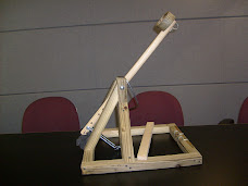
Then after many sittings of discussion combined with drawn out,clay modeled, and computer modeling we had composed our machine design. We chose to make a replica of a "clay-pigeon-shooter." Basically we ended up making a modern catapult.
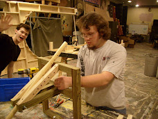
Next we discussed what type of material to use to build the launcher itself. We quickly decided wood was the most viable option because of its workability, low cost, and good looks.
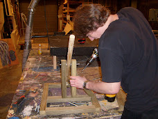
First we bought a 2"x4"x8' board that we cut in half down the center to double our usable materials and keep a low cost. We built the frame within the maximum parameters first. Then made vertical supports for the pivot arm. The pivot point was supported by 2, 1 1/2" x 1 3/4" boards that had front and side braces to help with the momentum that the swing arm generated. The springs were attached to the end of the swing arm and then to the inside base of the catapult. On the inside base of the catapult the springs are held in place by 2 eye-hooks that were secured into the base. Our machine could be adjusted by moving the place where the springs connect to the pivot arm. We made the adjustments and tested it to see where the ball landed. We used this method of trial and error until we were able to hit a makeshift target that was set at the proper distance. Then we would just hope that our machine would do the same thing every time.
Two conduit clips were screwed into the back of the catapult and a third was attached in to the end of the swing arm under the tennis ball holder. A 1/4" steel rod was inserted between the three clips to form a latch. After loading and aiming were complete, to fire we would quickly remove the rod which would release the swing arm and fire the catapult.
On testing day Mike spoke in front of the class and talked about the catapult. Meanwhile Scott had been in training for firing the devise so he was in charge of shooting. And keith was in full command of ball retrevial.
We ended up hitting the target 4 out of 6 times. We got an acceptible grade and in the end we were satisfied with out work because our project LOOKED better than any other launcher.
The best design was a mimic of a slingshot. It had an adjustible ramp and elastic cords to guide and propell the ball. It used a gate latch for a trigger. They hit the target 6 out of 6 times because their design gave the most consistant shot possible. Bravo.
The most interesting project used air propulsion. A bike pump and PVC pipe. It was shocking because it worked well and got a 4 out of 6 and cost under $8!
All in all was a good test of basic engineering and principals in physics. The project is an introduction into the uses of budgeting, time and material management and project designing.
This is an informational blog created by a group of college students for the purpose of educating high school students on what exactly engineers do. We know that there is confusion in this area for students in high school. So there will be a blog posting for each project assigned to us. It will discuss the engineering problem as it was told to us, our brain storming process, the solution we chose, and a final lookback at the project.
Our group consists of three freshman college students. Michael Graham, Mechanical Engineer. Keith Danaher, Electrical Engineer. Scott Rocca, Theatrical Design and Construction Management.
This was our first project assigned. Problem: to build a Tennis Ball Launcher within certain parameters. The part that makes this challenging is that the bounds of what we can do are very strict. The idea is to somehow propel a tennis ball twenty-five feet and hit a 22" target, centered two feet in the air. We would be given 6 shots at the target within 3 minutes; and grades are based on total number of hits! The devise which must do this has to cost under $8. And it has to be self contained within 18"L x 18"W x 20"H. And finally this miracle machine must be fired with a trigger mechanism.
We considered our options. Compressed air, torsion, springs and elastic cords were discussed among our group as possible methods for launching the tennis ball. After weighing the pros and cons ,we decided to use springs as the main propelling force. Springs would give us a very consistant force variable. Thus we could ideally adjust our machine to shoot and hit the same place every time on the target.
Then after many sittings of discussion combined with drawn out,clay modeled, and computer modeling we had composed our machine design. We chose to make a replica of a "clay-pigeon-shooter." Basically we ended up making a modern catapult.
Next we discussed what type of material to use to build the launcher itself. We quickly decided wood was the most viable option because of its workability, low cost, and good looks.
First we bought a 2"x4"x8' board that we cut in half down the center to double our usable materials and keep a low cost. We built the frame within the maximum parameters first. Then made vertical supports for the pivot arm. The pivot point was supported by 2, 1 1/2" x 1 3/4" boards that had front and side braces to help with the momentum that the swing arm generated. The springs were attached to the end of the swing arm and then to the inside base of the catapult. On the inside base of the catapult the springs are held in place by 2 eye-hooks that were secured into the base. Our machine could be adjusted by moving the place where the springs connect to the pivot arm. We made the adjustments and tested it to see where the ball landed. We used this method of trial and error until we were able to hit a makeshift target that was set at the proper distance. Then we would just hope that our machine would do the same thing every time.
Two conduit clips were screwed into the back of the catapult and a third was attached in to the end of the swing arm under the tennis ball holder. A 1/4" steel rod was inserted between the three clips to form a latch. After loading and aiming were complete, to fire we would quickly remove the rod which would release the swing arm and fire the catapult.
On testing day Mike spoke in front of the class and talked about the catapult. Meanwhile Scott had been in training for firing the devise so he was in charge of shooting. And keith was in full command of ball retrevial.
We ended up hitting the target 4 out of 6 times. We got an acceptible grade and in the end we were satisfied with out work because our project LOOKED better than any other launcher.
The best design was a mimic of a slingshot. It had an adjustible ramp and elastic cords to guide and propell the ball. It used a gate latch for a trigger. They hit the target 6 out of 6 times because their design gave the most consistant shot possible. Bravo.
The most interesting project used air propulsion. A bike pump and PVC pipe. It was shocking because it worked well and got a 4 out of 6 and cost under $8!
All in all was a good test of basic engineering and principals in physics. The project is an introduction into the uses of budgeting, time and material management and project designing.
Subscribe to:
Posts (Atom)