Dear Readers,
Hello again, we're glad to have another chance to interest you in learning about our engineering projects. Perhaps you''ll learn something new from our successes and/or failures! This month's project revolves around the field of civil engineering. The problem? To build the best bridge possible!
The Specifics: Of course this IS a college engineering course, so there has to be ridiculous restraints upon what we can build.
Firstly, the bridge can only be constructed from dowel rods and wood glue. Nothing else. It has to span a one meter gap and the trusses underneath can't touch anything (darn!)
Second, the bridge has to have a "road" surface on it so that a block of wood (5 cm x 5cm x 10 cm) representing a car can be able to move along the length of the deck unobstructed from beginning to end.
Third, we have to incorporate a loading platform consisting of a u-bolt and a piece of plywood, which sits underneath the bridge. This will enable the teacher to attach a hook with weights on it, to test the holding capacity of the bridge.
Fourth, the maximum cost of the bridge is only eight dollars!
Fifth, the bridge can't weigh any more than .75kg.
Sixth and final, the bridge can be any taller than 50cm.
Analysis: Well we had to take all of these constraints into consideration when we went through our brain storming process. Even with all of them holding us back, there are still a lot of options available for design of the structure. There are roof-like designs, which are based off of the whole structure being a triangle. These are similiar to arches. And there are the traditional truss bridge shapes, which are usually like parallelograms with lots of triangles inside. The main idea behind designing a bridge to be strong, is to divert the downward weight forces elsewhere. For instance a downward force on the tip of a trianlge divides the applied force in half to both sides of the triangle.
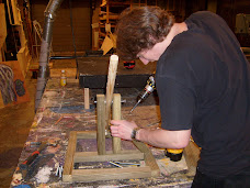
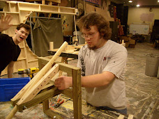
Process: First we chose from our available bridge designs which ones we liked. Then we had to make a build design with measurements of each component for each bridge. This task only requires simple arithmetic skills but it is tedious nonetheless. The point of which is obviously to calculate if the bridge idea would stay within the specifications.
We also have programs at our disposal, which do the more complicated math involving the diversion of the forces. With it we could put a 2-dimentional picture of our bridge in it, and test where the greatest and least stress points would be. With this information it was simple to decide which design we could derive the most strength from.
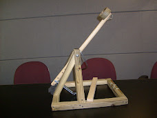
Our Solution: After much deliberation we ended up building a bridge supported by the Howe truss design. The joints where the dowel rods meet would attach with the tongue and groove method. We chose this because wood glue is stronger than the wood itself, so we want as much surface area in stress points to be covered in glue.
Our final bridge would be light-weight and costly. Both qualities are good because it gives the maximum possible advantages. It has triangles which divert the applied weight force to the central beams of the bridge. We realized that these beams would be taking in the most stress, so we glued the dowel rods together in three's to form the two main meter-long supports. This will make the downward forces work against the large surface area of the lengths of the glued rods. We predict that our bridge will be able to hold the weight of a person!
Subscribe to:
Post Comments (Atom)


1 comment:
Good pictures of the process and your work. However the text description is rather short and does not tell too much about the theory you followed in your design, and what were the lessons learned?
Please guide yourself using the evaluation rubric posted on the Blackboard.
Dr. Szabo
Post a Comment